(译)stackoverflow上关于柱形全景与立方体全景转换的讨论 - 一行代码一行泪 - 开源中国
提问:
@ WestLangley:
我正在给某网站开发一个简单的3D全景浏览功能。考虑到移动端的性能,我使用了three.js的CSS3 renderer。它需要一个由六张图组成功立方体贴图。
我用iPhone上的“Google Photosphere”(或其他类似的app)创建了一个2:1的柱形全景图,然后用这个网站(需要Flash)把柱形全景图转换成了立方体全景图。
但是我想自己完成这种转换,比如用three.js或者Photoshop。我发现Andrew Hazelden's好像用Photoshop做过类似的操作,但是没有那种直接转换的。有没有什么数学方法或者现成的js库可以做到的?尽量不要使用Blender这类3D软件来做。
也许实现会比较复杂,但是还是打算来问一下。本人js基础还阔以,但是用three.js没多久,因为WebGL在移动端好像跑起来有点慢,兼容性也一般,所以犹豫要不要用它的函数库。
提问下的回复:
@ Salix alba:可以通过在js中使用CSS或canvas做到,但是我不确定three.js是不是也可行:https://stackoverflow.com/questions/8912917/cutting-an-image-into-pieces-through-javascript
@ Eric Seifert: 我用一段python代码实现了:https://github.com/seiferteric/cubemap
最高票回答:
@ Salix alba
如果是要在服务端做的话选项有很多。http://www.imagemagick.org/里有一堆命令行工具可以对图片进行切割,你可以把这些命令放到你的代码里面,每次要转换的时候就执行。
很难说清楚这些命令里面用了哪些算法。我们可以通过一张正方形网格图片看看程序做了什么操作(译者注:有点拗口不好翻,大概就这意思)。我用维基上的一张网格图来示例。

转换后

通过这两张图可以看出立方体映射是如何映射的。
想象一下,有一个布满经纬线的球体被一个立方体包裹,然后从球的中心点投影到立方体上,产生一个扭曲的网格。
用数学来说明,有极坐标r,θ,ø,球半径 r = 1。 0 <θ<π,-π/4<ø<7π/ 4
x= r · sinθ · cosø
y= r · sinθ · sinø
z= r · cosθ
要把它们映射到立方体上,首先我们通过纬度范围 -π/4 < ø < π/4, π/4 < ø < 3π/4, 3π/4 < ø < 5π/4, 5π/4 < ø < 7π/4 将球体分成四个区块,它们会被投射到每个面的顶部或底部。
假设我们在第一个面(-π/4 < ø < π/4),sinθ · cos ø、sinθ · sin ø、cosθ 经过 中心投影到x=1的平面上后会变成a · sinθ · cosø、a · sinθ · sinø、a · cosθ。
因为 a·sinθ · cos ø = 1,所以 a = 1 / (sinθ · cosø)
因此投影后的点坐标为(1, tanø, cotθ / cosø)
如果 | cot θ / cos ø | < 1,这个坐标点会位于正面,否则就会出现在上面或下面,这时你就要使用另一套方法来计算投影。因为cosø最小值 = cosπ/ 4 = 1 / √2,所以如果cotθ/(1 /√2)>1或tanθ<1 / √2,投影点坐标一定是在上面。结果是θ<35º或0.615弧度
把上面的推算过程用python实现:
import sys
from PIL import Image
from math import pi,sin,cos,tan

def cot(angle):
    return 1/tan(angle)

# Project polar coordinates onto a surrounding cube
# assume ranges theta is [0,pi] with 0 the north poll, pi south poll
# phi is in range [0,2pi]
def projection(theta,phi):
        if theta<0.615:
            return projectTop(theta,phi)
        elif theta>2.527:
            return projectBottom(theta,phi)
        elif phi <= pi/4 or phi > 7*pi/4:
            return projectLeft(theta,phi)
        elif phi > pi/4 and phi <= 3*pi/4:
            return projectFront(theta,phi)
        elif phi > 3*pi/4 and phi <= 5*pi/4:
            return projectRight(theta,phi)
        elif phi > 5*pi/4 and phi <= 7*pi/4:
            return projectBack(theta,phi)

def projectLeft(theta,phi):
        x = 1
        y = tan(phi)
        z = cot(theta) / cos(phi)
        if z < -1:
            return projectBottom(theta,phi)
        if z > 1:
            return projectTop(theta,phi)
        return ("Left",x,y,z)

def projectFront(theta,phi):
        x = tan(phi-pi/2)
        y = 1
        z = cot(theta) / cos(phi-pi/2)
        if z < -1:
            return projectBottom(theta,phi)
        if z > 1:
            return projectTop(theta,phi)
        return ("Front",x,y,z)

def projectRight(theta,phi):
        x = -1
        y = tan(phi)
        z = -cot(theta) / cos(phi)
        if z < -1:
            return projectBottom(theta,phi)
        if z > 1:
            return projectTop(theta,phi)
        return ("Right",x,-y,z)

def projectBack(theta,phi):
        x = tan(phi-3*pi/2)
        y = -1
        z = cot(theta) / cos(phi-3*pi/2)
        if z < -1:
            return projectBottom(theta,phi)
        if z > 1:
            return projectTop(theta,phi)
        return ("Back",-x,y,z)

def projectTop(theta,phi):
        # (a sin θ cos ø, a sin θ sin ø, a cos θ) = (x,y,1)
        a = 1 / cos(theta)
        x = tan(theta) * cos(phi)
        y = tan(theta) * sin(phi)
        z = 1
        return ("Top",x,y,z)

def projectBottom(theta,phi):
        # (a sin θ cos ø, a sin θ sin ø, a cos θ) = (x,y,-1)
        a = -1 / cos(theta)
        x = -tan(theta) * cos(phi)
        y = -tan(theta) * sin(phi)
        z = -1
        return ("Bottom",x,y,z)

# Convert coords in cube to image coords
# coords is a tuple with the side and x,y,z coords
# edge is the length of an edge of the cube in pixels
def cubeToImg(coords,edge):
    if coords[0]=="Left":
        (x,y) = (int(edge*(coords[2]+1)/2), int(edge*(3-coords[3])/2) )
    elif coords[0]=="Front":
        (x,y) = (int(edge*(coords[1]+3)/2), int(edge*(3-coords[3])/2) )
    elif coords[0]=="Right":
        (x,y) = (int(edge*(5-coords[2])/2), int(edge*(3-coords[3])/2) )
    elif coords[0]=="Back":
        (x,y) = (int(edge*(7-coords[1])/2), int(edge*(3-coords[3])/2) )
    elif coords[0]=="Top":
        (x,y) = (int(edge*(3-coords[1])/2), int(edge*(1+coords[2])/2) )
    elif coords[0]=="Bottom":
        (x,y) = (int(edge*(3-coords[1])/2), int(edge*(5-coords[2])/2) )
    return (x,y)

# convert the in image to out image
def convert(imgIn,imgOut):
    inSize = imgIn.size
    outSize = imgOut.size
    inPix = imgIn.load()
    outPix = imgOut.load()
    edge = inSize[0]/4   # the length of each edge in pixels
    for i in xrange(inSize[0]):
        for j in xrange(inSize[1]):
            pixel = inPix[i,j]
            phi = i * 2 * pi / inSize[0]
            theta = j * pi / inSize[1]
            res = projection(theta,phi)
            (x,y) = cubeToImg(res,edge)
            #if i % 100 == 0 and j % 100 == 0:
            #   print i,j,phi,theta,res,x,y
            if x >= outSize[0]:
                #print "x out of range ",x,res
                x=outSize[0]-1
            if y >= outSize[1]:
                #print "y out of range ",y,res
                y=outSize[1]-1
            outPix[x,y] = pixel

imgIn = Image.open(sys.argv[1])
inSize = imgIn.size
imgOut = Image.new("RGB",(inSize[0],inSize[0]*3/4),"black")
convert(imgIn,imgOut)
imgOut.show()
projection函数接收theta和phi两个参数并返回其投影在球体上的坐标(范围是-1~1)。
cubeToImg函数接收一个包含xyz坐标的元组和立方体边长输出到图片坐标系中

网上找了一张全景图,用上面的算法对其进行转换以后,得到了正确的形状:
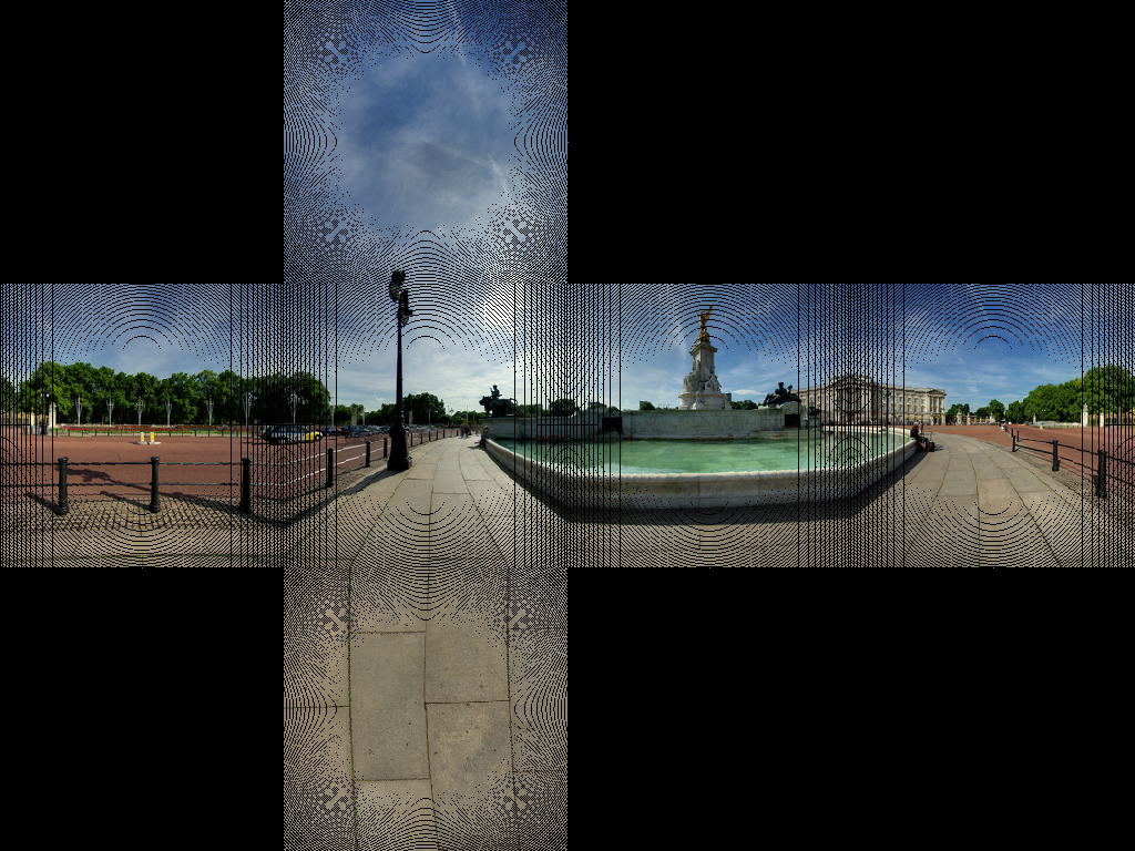
好像只有大部分的线是铺对的,又一部分图像没有任何像素,这是因为像素投影没有一 一对应,我们需要再做一次逆转换。先在源图像上遍历每个像素,然后在目标图像上找到每个对应的点。接着遍历目标图像,在对应的原图像上找到最近的像素。
修改代码后:
import sys
from PIL import Image
from math import pi,sin,cos,tan,atan2,hypot,floor
from numpy import clip
# get x,y,z coords from out image pixels coords
# i,j are pixel coords
# face is face number
# edge is edge length
def outImgToXYZ(i,j,face,edge):
a = 2.0*float(i)/edge
b = 2.0*float(j)/edge
if face==0: # back
(x,y,z) = (-1.0, 1.0-a, 3.0 - b)
elif face==1: # left
(x,y,z) = (a-3.0, -1.0, 3.0 - b)
elif face==2: # front
(x,y,z) = (1.0, a - 5.0, 3.0 - b)
elif face==3: # right
(x,y,z) = (7.0-a, 1.0, 3.0 - b)
elif face==4: # top
(x,y,z) = (b-1.0, a -5.0, 1.0)
elif face==5: # bottom
(x,y,z) = (5.0-b, a-5.0, -1.0)
return (x,y,z)
# convert using an inverse transformation
def convertBack(imgIn,imgOut):
inSize = imgIn.size
outSize = imgOut.size
inPix = imgIn.load()
outPix = imgOut.load()
edge = inSize[0]/4 # the length of each edge in pixels
for i in xrange(outSize[0]):
face = int(i/edge) # 0 - back, 1 - left 2 - front, 3 - right
if face==2:
rng = xrange(0,edge*3)
else:
rng = xrange(edge,edge*2)
for j in rng:
if j<edge:
face2 = 4 # top
elif j>=2*edge:
face2 = 5 # bottom
else:
face2 = face
(x,y,z) = outImgToXYZ(i,j,face2,edge)
theta = atan2(y,x) # range -pi to pi
r = hypot(x,y)
phi = atan2(z,r) # range -pi/2 to pi/2
# source img coords
uf = ( 2.0*edge*(theta + pi)/pi )
vf = ( 2.0*edge * (pi/2 - phi)/pi)
# Use bilinear interpolation between the four surrounding pixels
ui = floor(uf) # coord of pixel to bottom left
vi = floor(vf)
u2 = ui+1 # coords of pixel to top right
v2 = vi+1
mu = uf-ui # fraction of way across pixel
nu = vf-vi
# Pixel values of four corners
A = inPix[ui % inSize[0],clip(vi,0,inSize[1]-1)]
B = inPix[u2 % inSize[0],clip(vi,0,inSize[1]-1)]
C = inPix[ui % inSize[0],clip(v2,0,inSize[1]-1)]
D = inPix[u2 % inSize[0],clip(v2,0,inSize[1]-1)]
# interpolate
(r,g,b) = (
A[0]*(1-mu)*(1-nu) + B[0]*(mu)*(1-nu) + C[0]*(1-mu)*nu+D[0]*mu*nu,
A[1]*(1-mu)*(1-nu) + B[1]*(mu)*(1-nu) + C[1]*(1-mu)*nu+D[1]*mu*nu,
A[2]*(1-mu)*(1-nu) + B[2]*(mu)*(1-nu) + C[2]*(1-mu)*nu+D[2]*mu*nu )
outPix[i,j] = (int(round(r)),int(round(g)),int(round(b)))
imgIn = Image.open(sys.argv[1])
inSize = imgIn.size
imgOut = Image.new("RGB",(inSize[0],inSize[0]*3/4),"black")
convertBack(imgIn,imgOut)
imgOut.save(sys.argv[1].split('.')[0]+"Out2.png")
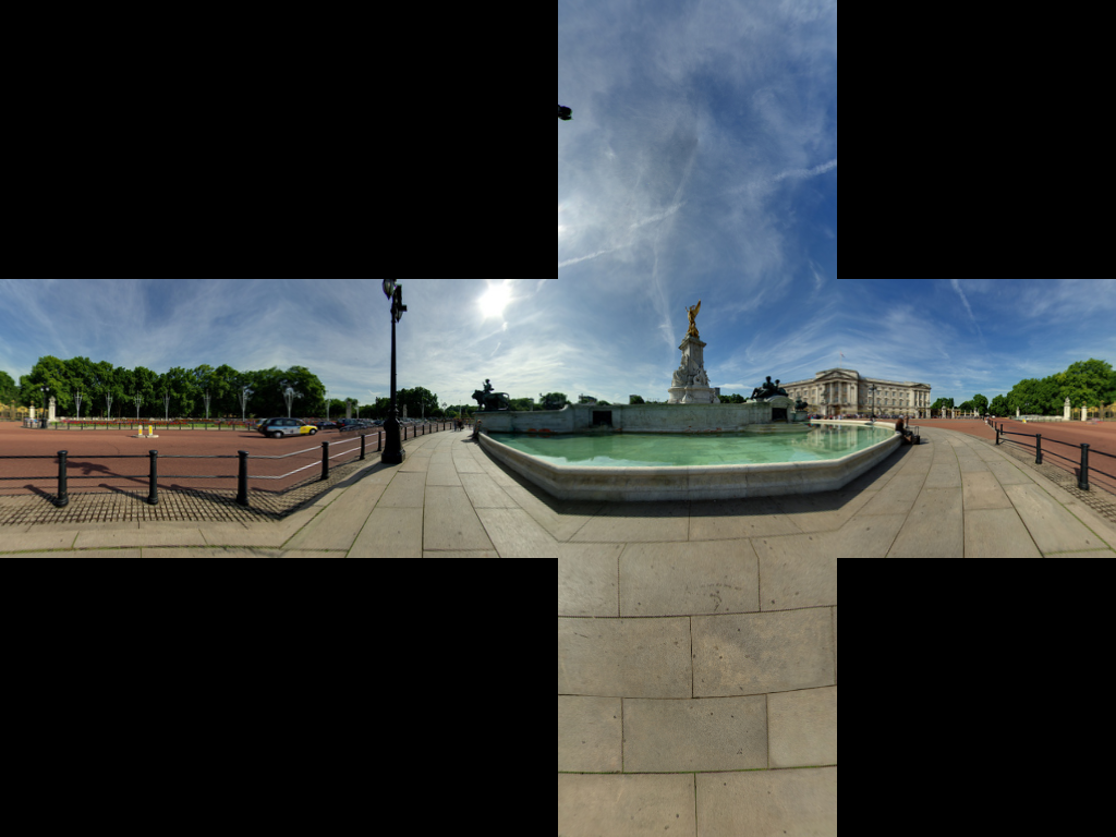
imgOut.show()重新生成后的结果:
英文好的可以看原文:https://stackoverflow.com/questions/29678510/convert-21-equirectangular-panorama-to-cube-map,有翻译上的问题欢迎指出。
后面的回复还有不少干货,有空我会继续翻译
原网址: 访问
创建于: 2018-10-13 16:38:25
目录: default
标签: 无
未标明原创文章均为采集,版权归作者所有,转载无需和我联系,请注明原出处,南摩阿彌陀佛,知识,不只知道,要得到


最新评论